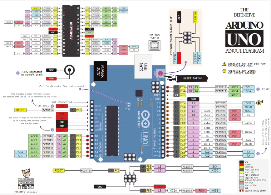
Arduino Uno & ATmega328 Pin-Map
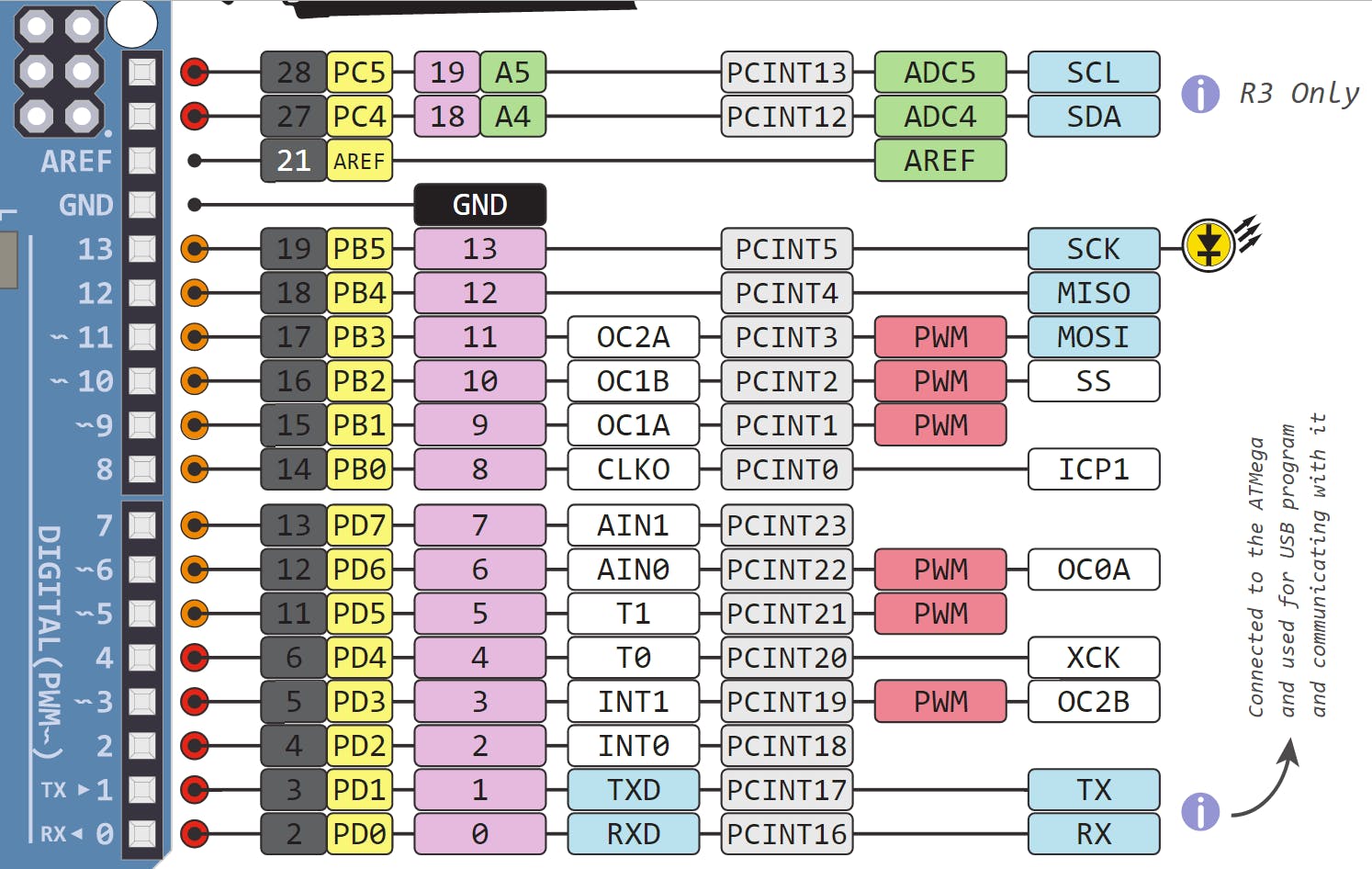
※ Pin 읽기
16/PB2-10-OC1B-PCINT2-PWM-SS
16/PB2 : Micro Controller PortB 2에 해당한다는 내용
10 : Arduino 10번에 연결되어 있다는 내용
OC1B : Timer1(OsilliCator) B에 연결되어 있다는 내용
PCINT2 : Pin변경 Interrupt2에 해당한다는 내용
PWM : 해당 Pin은 PWM을 생성할 수 있다는 내용
SS : SPI 통신에서 SS( Slave Select)으로 사용될 수 있다는 내용
★ Tip
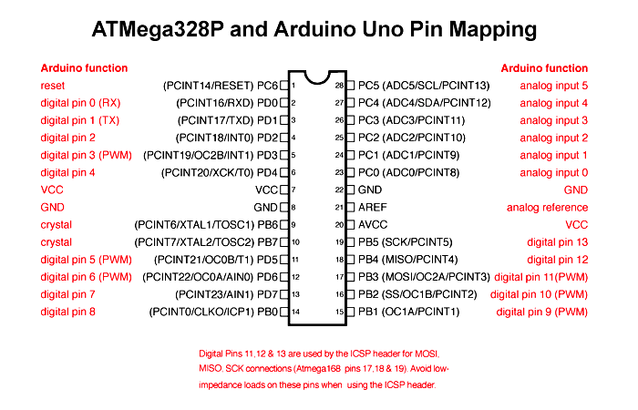
- Chip과 Micro Prossecor 모두 찾아봐야 함!!!!!!!!!!!!!
Arduino 주요 파라미터 정리
INPUT & LOW : 0x0
OUTPUT & HIGH : 0x1
< Arduino Register로 접근하기 >
PinMode
- 특정 Port를 Input or Output할껀지 정하는 코드
ex)
pinMode(PIN_MOTOR_LEFT_FORWARD, OUTPUT);
- PIN_MOTOR_LEFT_FORWARD 해당 Pin을 OUTPUT으로 설정한다는 것
하지만 직접 Register를 조작하는게 더 빠름!
ex)
#define PIN_MOTOR_LEFT_FORWARD 10
=> PIN_MOTOR_LEFT_FORWARD를 10번 Port(PB2)에 할당
=> 10번 Port는 DDRB Register와 연결됨
<ATmega328P Register>
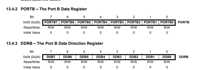
DDRB |= (1 << DDB2);
=> 이렇게 하면 해당 포트가 Output으로 활성화!!
< Arduino Uno & ATmega328 Pin-Map >
Line Tracer Arduino code
#include <IRremote.h>
#define PIN_IR_RECEIVE 2
#define PIN_MOTOR_LEFT_FORWARD 10
#define PIN_MOTOR_LEFT_BACKWARD 9
#define PIN_MOTOR_RIGHT_FORWARD 6
#define PIN_MOTOR_RIGHT_BACKWARD 5
// Sensor Input
#define PIN_LINE_DETECT_RIGHT A0
#define PIN_LINE_DETECT_LEFT A1
#define REF_VALUE_LINE_DETECT 500
#define BLACK 550
#define WHITE 30
#define TRUE 1
#define FALSE 0
uint16_t targetSensor = (BLACK - WHITE) / 2;
float motorSpeedLeft = 0; // -255~255
float motorSpeedRight = 0; // -255~255
int isStartLineTracing = 0;
void setup() {
Serial.begin(115200);
// Open Port
DDRB |= (1<<DDB2 | 1 << DDB1);
DDRD |= (1 << DDD2 | 1 << DDD6 | 1 << DDD5);
Timer_setup();
// 차례대로 register write
OCR1B = 0;
OCR1A = 0;
OCR0A = 0;
OCR0B = 0;
ADC_setup();
Serial.begin(115200);
}
void loop() {
// put your main code here, to run repeatedly:
uint16_t valueRight, valueLeft;
float Left_PIDOut, Right_PIDOut;
static unsigned long lastDebugTime = 0;
unsigned long currentTime = millis();
processIrReceiver();
if(isStartLineTracing == 1) {
// Read data from A0 & A1
valueRight = ADC_val(0);
valueLeft = ADC_val(1);
Left_PIDOut = PID(targetSensor, valueLeft);
Right_PIDOut = PID(targetSensor, valueRight);
}
else {
motorSpeedLeft = 200;
motorSpeedRight = 200;
}
processMotor();
if (currentTime - lastDebugTime > 500) {
Serial.print("Left Speed: ");
Serial.print(motorSpeedLeft);
Serial.print(" | Right Speed: ");
Serial.print(motorSpeedRight);
Serial.print(" | OCR1A: ");
Serial.print(OCR1A);
Serial.print(" | OCR1B: ");
Serial.print(OCR1B);
Serial.print(" | OCR0A: ");
Serial.print(OCR0A);
Serial.print(" | OCR0B: ");
Serial.println(OCR0B);
lastDebugTime = currentTime;
}
}
// Timer
void Timer_setup() {
// Set Timer1
TCCR1A = 0;
TCCR1B = 0;
TCCR1A = (1 << WGM10 | 1 << WGM11 | 1 << COM1A1 | 1 << COM1B1); // 8비트 Fast PWM & 비반전 모드
TCCR1B = (1 << WGM12) | (1 << CS10); // no prescaling
// Set Timer0
TCCR0A = 0;
TCCR0B = 0;
TCCR0A = (1 << WGM01 | 1 << WGM00 | 1 << COM0A1 | 1 << COM0B1); // 8비트 Fast PWM & 비반전 모드
TCCR0B = (1 << CS00); // no prescaling
}
//ADC
void ADC_setup() {
// for Analog read AVcc
ADMUX = 0;
ADMUX = (1 << REFS0);
// ADC Prescalor 128
ADCSRA = 0;
ADCSRA = (1 << ADEN) | (1 << ADPS2) | (1 << ADPS1) | (1 << ADPS0);
}
uint16_t ADC_val(int num) {
ADMUX = (ADMUX & 0xF8) | num;
ADCSRA |= (1 << ADSC); // ADSC : ADC Start Conversion
while (ADCSRA & (1 << ADSC)); // waiting
return ADC;
}
// PID
float PID(float desired, float current)
{
float Kp = 0.8;
float Ki = 0.5;
float Kd = 0.03;
float PControl;
static float IControl;
float DControl;
float PIDControl;
static int errorPrevious;
int errorCurrent;
errorCurrent = desired - current;
// error > 0 : WHITE 에 가까움.
// error < 0 : BLACK 에 가까움.
PControl = Kp * errorCurrent;
IControl += Ki * errorCurrent;
IControl = constrain(IControl, -100, 100);
DControl = Kd * (errorCurrent - errorPrevious);
PIDControl = PControl + IControl + DControl;
PIDControl = constrain(PIDControl, -100, 100);
errorPrevious = errorCurrent;
return PIDControl;
}
// Motor PreProcessor
void processMotor(void)
{
if(motorSpeedLeft >= 0)
{
OCR1A = (uint8_t)min(motorSpeedLeft, 255);
OCR1B = 0;
}
else
{
OCR1A = 0;
OCR1B = (uint8_t)min(-motorSpeedLeft, 255);
}
if(motorSpeedRight >= 0)
{
OCR0A = (uint8_t)min(motorSpeedRight, 255);
OCR0B = 0;
}
else
{
OCR0A = 0;
OCR0B = (uint8_t)min(-motorSpeedRight, 255);
}
}
// remote controller preprocessor
void processIrReceiver(void)
{
if (IrReceiver.decode() == true) // 리모컨으로부터 받은 신호가 있으면
{
if (IrReceiver.decodedIRData.protocol == NEC) {
Serial.println(IrReceiver.decodedIRData.command, HEX); //받은 신호를 시리얼 모니터에 입력
if(IrReceiver.decodedIRData.command == 0x16) // *
{
Serial.println("start");
isStartLineTracing = 1;
}
else if(IrReceiver.decodedIRData.command == 0x0D) // #
{
Serial.println("stop");
isStartLineTracing = 0;
}
}
IrReceiver.resume(); // 다음 신호 수신
}
}
=> Register로 Port Open & PWM Mode 설정, PWM 값 입력!!
=> 오른쪽 모터는 회전, 왼쪽은 회전X, 원인을 모르겠다....

추후 수정 예정..............